Timestamps in UPAS log files In log files written by Ultrasonic Personal Air Samplers (UPAS),...
Access Sensor Technologies has improved our UPAS v2.1 and UPAS v2.1 PLUS firmware to make UPAS operation more intuitive and reliable. Read on to learn how the new firmware (version 200) differs from our old firmware (versions < 200). You'll find out if upgrading to firmware version 200 is the right decision for you.
What is firmware?
The firmware is the software that runs on the UPAS. The firmware tells the UPAS how to operate and when to complete tasks.
Can any UPAS be updated to firmware version 200?
Firmware version 200 is compatible with all UPAS v2.1 and UPAS v2.1 PLUS (any device with a serial number that starts with "PSP") but is NOT compatible with UPAS v2.0.
If you're using custom firmware, contact our team before updating your UPAS to ensure your custom features remain intact. Examples of custom firmware include revision numbers 158, 159, 160, or 277.
What's new in UPAS firmware version 200?
Firmware version 200 offers several benefits over older firmware versions. These changes are discussed in more detail in the sections that follow. Click on the linked text in the list below to learn more.
- More intuitive LED indicators: Firmware version 200 uses fewer colors and fewer flashing lights to convey the most important information about the UPAS status.
- No more going outside to get a GPS signal before programming a sample if the UPAS internal clock is set incorrectly upon power-on: With firmware version 200, the UPAS gets the time from the mobile device used to program the sample.
- More reliable UPAS operation: Have you ever lost a UPAS sample due to an RTOS crash? That won't happen with firmware version 200.
- Improved error handling if the microSD card is removed during a sample: Firmware version 200 make it easier to restart or reprogram the sample after the microSD card is reinserted.
- Greater transparency in reporting sample flow rates and volumes: Log files written with firmware version 200 include flow rates and sample volumes (a) calculated using our factory calibration as well as (b) calculated with the calibration curve adjusted in accordance with the user-specified flow offset.
- Streamlined sample log files: We've reduced the number of variables included in our standard sample log (mostly by removing values that served development or troubleshooting purposes) to reduce log file sizes and make UPAS data easier to work with.
- More accurate battery charge percentage readings: With firmware versions < 200 the charge percentage might have sometimes been reported (incorrectly) as 100% when the UPAS was powered on after the battery had been fully-depleted. That won't happen with firmware version 200.
- Updated mobile applications: We've released new versions of the AST UPAS app for iOS (version 1.1.2) and Android (version 2.3.1) mobile devices.
Does firmware version 200 affect the log file format?
No, firmware version 200 writes log files with the same format as firmware version 157. With firmware version 200, you will still be able to read UPAS log files into R using our astr package and visualize log file data using our web-based R Shiny application; however, a few variable names have changed, a few new variables have been added, and some variables have been removed from the standard log file. Read the Greater transparency in reporting sample flow rates and volumes and Streamlined sample log files sections to learn more.
More intuitive LED indicators
With firmware versions < 200, the LED flashed a lot of different colors during UPAS start-up. Each flash conveyed information about the UPAS status, but it wasn't easy to keep track of what all the flashes meant.
In firmware version 200, the number of LED colors and flashes displayed during UPAS power-on and sample start-up has been simplified to convey the most important information about the UPAS status. Tables 1–4 below describe the new LED indicators. See the updated UPAS v2.1 and v2.1 PLUS User Guide for more information.
Table 1. UPAS power-on sequence (firmware version 200)
| Power-on sequence | LED status | Meaning | |
| 1 | Power-on UPAS by pressing pushbutton for > 3 s | White LED on | UPAS is powered on and initializing |
| 2 | Battery State of Charge (SOC)1 indication (UPAS flashes one of these codes). If the UPAS is charging, the SOC code will appear twice (8× flashes total). |
Red LED flashes 4×
Orange LED flashes 4×
Yellow LED flashes 4×
Blue LED flashes 4×
Green LED flashes 4×
|
SOC is < 25%
SOC is 25 to 50%
SOC is 50 to 75%
SOC is 75 to 96%
SOC is > 96%
|
| 3 | Check for microSD card | White LED on | Checks whether a microSD card is installed |
| 4 | Wait for microSD card installation if not already installed2 | White LED flashes indefinitely until microSD card is installed | No microSD card is installed in the UPAS |
| 5 | Get sensor information and check "At Next Power-On" state3 | White LED on | UPAS is checking sensor settings and determining whether it should proceed to starting a sample |
| 6 | Power on Bluetooth® Low Energy (BLE) | White LED on | Powering on BLE to allow for Android/iOS app programming |
| 7 | UPAS is ready to connect to the iOS/Android app to program a sample |
Pink LED flashing or
pink LED on
|
Flashing pink: A GPS signal has not been received.4
Solid pink: A GPS signal has been received.5
|
| 8 | UPAS is connected to the app | Blue/pink alternating LED or blue LED on | Blue/pink alternating: A GPS signal has not been received.4 Solid blue: A GPS signal has been received.5 |
|
|||
Table 2. Sample start sequence when the sample Start Time is set to Now, At Next Power-On, and Set Date/Time, respectively (firmware version 200).
| Step | LED status | The UPAS is... |
|
| Now | Sample initiating | Lilac LED on | Initiating the pre-programmed sample; pumps will start soon and will adjust to the flow rate setpoint. |
| Targeting set flow rate | Green LED flashing1,2 | Adjusting the sampling pumps to the flow rate setpoint. | |
| Sample running | Green LED on (or blue LED on if charging or pink LED on if fully-charged) | Controlling the flow rate to the setpoint that is required for the inlet selected by the user during sample programmed. | |
| At Next Power-On | Waiting for next power-on | LED off | Off and awaiting power-on (via the pushbutton) to initiate the pre-programmed sample. |
| Power-on with pushbutton | Follows UPAS power-on sequence with "At Next Power-On" state enabled | Powered-on (because the user has held down the pushbutton for 3 s). | |
| Sample initiating | Lilac LED on | Initiating the pre-programmed sample; pumps will start soon and will adjust to the flow rate setpoint. | |
| Targeting set flow rate | Green LED flashing1,2 | Adjusting the sampling pumps to the flow rate setpoint. | |
| Sample running | Green LED on (or blue LED on if charging or pink LED on if fully-charged) | Controlling the flow rate to the setpoint that is required for the inlet selected by the user during sample programmed. | |
| Set Date/Time | Waiting for start date/time | Blue LED flashes repeatedly | Awaiting the scheduled start date/time to initiate the pre-programmed sample. |
| Sample initiating | Lilac LED on | Initiating the pre-programmed sample; pumps will start soon and will adjust to the flow rate setpoint. | |
| Targeting set flow rate | Green LED flashing1,2 | Adjusting the sampling pumps to the flow rate setpoint. | |
| Sample running | Green LED on (or blue LED on if charging or pink LED on if fully-charged) | Controlling the flow rate to the setpoint that is required for the inlet selected by the user during sample programmed. | |
|
|||
Table 3. UPAS LED indicators when actively running a sample. These have not changed between firmware version 157 and 200.
| LED color | Meaning | Recommended action |
| Green | UPAS is sampling and not charging. | No action required |
| Blue | UPAS is sampling and charging. | No action required |
| Pink | UPAS is sampling and fully-charged. | No action required |
| Orange | UPAS battery is low (approximately 20% charge remaining). | Plug the UPAS into a charging source while the sample is running. |
| Red1 | UPAS flow is obstructed or the pumps are at maximum power.1 | Verify that the inlet is not obstructed. |
|
||
Table 4. UPAS LED indicators in Filter Flow Check & Adjust (iOS app) or Filter Flow Offset (Android app) mode (firmware version 200).
| LED color | Meaning |
| Lilac LED flashing | The UPAS flow rate is still adjusting to the target value associated with the current flow offset setting. |
| Lilac LED on | The UPAS flow rate has adjusted to the target value associated with the current flow offset setting. |
Why does the UPAS no longer need to get a GPS signal to set the internal clock before programming samples?
The UPAS needs to know the date and time to function properly, so a UPAS operating on the old firmware (versions < 200) would not connect to a mobile device for sample programming if there was not a valid timestamp stored in the UPAS internal memory. Additionally, a UPAS operating on the old firmware could only get the Coordinated Universal Time (UTC) from a GPS satellite. If the UPAS lost track of time (e.g., because the UPAS battery depleted to such a low state of charge that the timestamp stored in the UPAS internal memory was lost), the UPAS LED would flash pink upon power-on, the UPAS would not connect to the mobile app, and the UPAS would need to be taken outside to connect to a GPS satellite before a sample could be programmed or started.
A UPAS operating on the new firmware (version 200) gets the UTC timestamp from the mobile device used to program a sample. As a result, the UPAS no longer needs to connect to a GPS satellite to get the time. A UPAS operating on firmware version 200 can connect to a mobile device upon power-on regardless of whether the UPAS has the current date and time stored in the internal UPAS memory. The timestamps that the UPAS gets from mobile devices will be just as accurate as the timestamps the UPAS used to get from GPS satellites because mobile devices get Coordinated Universal Time from the cellular network, Wi-Fi, or GPS.
This change in the procedure used to set the UPAS internal clock makes it easier to use the UPAS in locations with poor GPS signal. This change also makes it easier to see if the UPAS has a GPS signal for location tracking when programming and starting the sample. Previously, the LED was always solid pink when the UPAS was ready to connect to the mobile app. Now, the UPAS can connect to the mobile app when the LED is either flashing pink (no GPS signal) or solid pink (GPS signal received). See Figure 1 for a summary of this behavior and Table 1 for additional information.
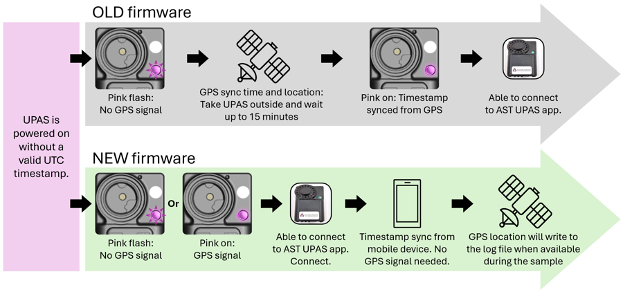
Figure 1. Old versus new (i.e., firmware version ≤ 200 versus firmware version 200) behavior when the UPAS is powered-on without a valid UTC timestamp stored in the UPAS internal memory.
What will happen if the microSD card is removed during the sample? How do I get the UPAS to start sampling again?
If the microSD card is removed during a sample, a UPAS operating on the old firmware (versions < 200) would continue to sample for 5 minutes. If the microSD card was reinserted during that 5-minute period, the sample would continue to run, but the sample log data from the period when the microSD card was removed would never be written to the log file. If the microSD card was not reinserted within 5 minutes, the UPAS would stop sampling and shut down.
A UPAS operating on the new firmware (version 200) will immediately stop sampling, reset, and go through the power-on sequence described in Table 1 if the microSD card is removed. Firmware version 200 firmware will then allow you to restart or reprogram the sample using one of these methods:
- Restart with the same settings:
- While the microSD card is removed and the LED is flashing white, press the pushbutton. The LED will switch to flashing orange.
- Reinsert the microSD card to start a new sample with the same settings as the original.
- Note #1: If the UPAS is programmed to run a timed sample, the sample timer will reset when the sample is restarted using this method. For example, a sample that was programmed to run for 24 hours will run for a full 24 hours after the restart, regardless of how long the sample ran before the microSD card was removed. To end the sample early, you can turn off the UPAS manually by holding down the pushbutton for more than 3 seconds. If you want the UPAS to shut off automatically after a different duration than the one that was previously programmed, reprogram the sample using Method 2 below.
-
- Note #2: The log file name will use the lifetime sample count in place of the original sample name, but the original sample name and cartridge ID will be preserved within the log file. This file name change will indicate that the microSD card was removed mid-sample and the sample was restarted.
- Reprogram the sample:
- Reinsert the microSD card while the LED is flashing white.
- Allow the UPAS to complete the power-on sequence (Table 1); then, connect the UPAS to mobile app, reprogram the sample settings, and start sampling with the new settings.
Greater transparency in reporting sample flow rates and volumes
The UPAS contains a mass flow sensor that monitors the flow rate through the sample filter continuously throughout the sample. The UPAS uses data from this mass flow sensor—along with data on the air temperature, pressure, and relative humidity—to adjust the pump power, as needed, to maintain the target volumetric flow rate through the sample filter. We calibrate the mass flow sensor at our factory when the UPAS is manufactured or serviced. If you check the UPAS filter sample flow rate against an external reference flow meter and apply a nonzero flow offset (using the “Filter Flow Check & Adjust” feature in the mobile app), that has the effect of shifting the factory calibration curve.
With firmware versions < 200, only sample flow rates and volumes calculated with the calibration curve shifted in accordance with the user-supplied flow offset were written to the log file.
With firmware version 200, sample flow rates and volumes calculated using the factory calibration curve alone (i.e., without accounting for the flow offset) are also written to every log file. As a result:
- Three new variables have been added to the log file header: OverallFlowAvgFactory, PumpingFlowAvgFactory, and SampledVolumeFactory (see Table 5).
- The header parameters that were previously named OverallFlowRateAverage, PumpingFlowRateAverage, and SampledVolume have been renamed OverallFlowAvgOffset, PumpingFlowAvgOffset, and SampledVolumeOffset. When the
read_ast_header()function from the astr package is used withupdate_names = TRUE, the relevant parameters in log files written using older firmware versions will be updated to these new names. - Four new variables have been added to the sample log: PumpingFlowFactory, OverallFlowFactory, SampledVolumeFactory, and PM2_5SampledMassFactory.
- The variables in the sample log that were previously named PumpingFlowRate, OverallFlowRate, SampledVolume, and PM2_5SampledMass have been renamed PumpingFlowOffset, OverallFlowOffset, SampledVolumeOffset, and PM2_5SampledMassOffset. When the
read_ast_log()function from the astr package is used withupdate_names = TRUE, the relevant variables in log files written using older firmware versions will be updated to these new names.
Table 5. Variables used to summarize sample flow rates and volumes in log files written using firmware versions 200 and 157. For each metric, the variable name used in log files written with firmware version 200 is shown first, followed by the variable name used in log files written with firmware version 157 (if applicable).
| Firmware | Variable name | Units | Meaning |
| LOG FILE HEADER | |||
| 200 | OverallFlowAvgFactory | (L min-1) | Sample-averaged flow rate through the filter as calculated using our factory calibration curve. |
| 200 | PumpingFlowAvgFactory | (L min-1) | Sample-averaged flow rate through the filter when the pumps were on as calculated using our factory calibration curve. |
| 200 | SampledVolumeFactory | (L) | Volume of air sampled through the filter as calculated using our factory calibration curve. |
| 200 157 |
OverallFlowAvgOffset OverallFlowRateAverage |
(L min-1) | Sample-averaged flow rate through the filter as calculated with the calibration curve shifted by the user-applied flow offset; will equal OverallFlowAvgFactory if FlowOffset = 0. |
| 200 157 |
PumpingFlowAvgOffset PumpingFlowRateAverage |
(L min-1) | Sampled-averaged flow rate through the filter when the pumps were on as calculated with the calibration curve shifted by the user-applied flow offset; will equal PumpingFlowAvgFactory if FlowOffset = 0. |
| 200 157 |
SampledVolumeOffset SampledVolume |
(L) | Volume of air sampled through the filter as calculated with the calibration curve shifted by the user-applied flow offset; will equal SampledVolumeFactory if FlowOffset = 0 |
| SAMPLE LOG | |||
| 200 | PumpingFlowFactory | (L min-1) | The volumetric flow rate through the sample filter as calculated using our factory calibration curve. If the log interval = 30 s, this is the time-average of the flow rate measured when the pumps were active. If the log interval = 1 s, this is the instantaneous flow rate (when the pumps were active) or zero (when the pumps were inactive). |
| 200 | OverallFlowFactory | (L min-1) | Duty cycle-adjusted flow rate through the sample filter as calculated using our factory calibration curve; equal to PumpingFlowFactory multiplied by the duty cycle. |
| 200 | SampledVolumeFactory | (L) | Cumulative volume of air sampled through the filter as calculated using our factory calibration curve. |
| 200 157 |
PumpingFlowOffset PumpingFlowRate |
(L min-1) | The volumetric flow rate through the sample filter as calculated with the calibration curve shifted by the user-applied flow offset; will be equal to PumpingFlowFactory if FlowOffset = 0. If the log interval = 30 s, this is the time-average of the flow rate measured when the pumps were active. If the log interval = 1 s, this is the instantaneous flow rate (when the pumps were active) or zero (when the pumps were inactive). |
| 200 157 |
OverallFlowOffset OverallFlowRate |
(L min-1) | Duty-cycle adjusted flow rate through the sample filter as calculated with the calibration curve shifted by the user-applied flow offset; equal to PumpingFlowOffset multiplied by the duty cycle; will equal OverallFlowFactory when FlowOffset = 0. |
| 200 157 |
SampledVolumeOffset SampledVolume |
(L) | Cumulative volume of air sampled through the filter as calculated with the calibration curve shifted by the user-applied flow offset; will equal SampledVolumeFactory when FlowOffset = 0. |
| 200 | PM2_5SampledMassFactory | (μg) | Cumulative mass of PM2.5 sampled onto the filter as estimated from PM2_5MC and SampledVolumeFactory |
|
200 |
PM2_5SampledMassOffset PM2_5SampledMass |
(μg) | Cumulative mass of PM2.5 sampled onto the filter as estimated from PM2_5MC and SampledVolumeOffset |
Streamlined sample log files
To reduce the size and complexity of UPAS v2.1 and v2.1 PLUS log files, the variables listed in Table 6 are no longer included in standard log files written using firmware version 200. These variables were either: (a) included in sample logs written using firmware versions < 200 primarily for troubleshooting purposes or (b) are not relevant in most sampling applications. See our UPAS v2.1 and v2.1 PLUS User Guide for detailed descriptions of these variables.
If you want to collect larger sample logs that still include all the variables listed in Table 6 (except Dead, BCS1, BCS2, BC_NPG), you can put your UPAS into “verbose logging mode” by connecting it to the mobile app, entering “LOGVERBOSE#” (without quotes) in the sample name field, and then hitting “return” (on an iOS device) or “Ok” (on an Android device). The app will return to the main menu, “LOGVERBOSE#” will disappear from the sample name field, and the mode will have been activated.
Table 6. These variables were included in sample logs written using firmware version 157 but are no longer included in standard sample logs written using firmware version 200.
| Sample log category | Variables that have been removed from the standard sample log |
| DateTime | UnixTimeMCU |
| Motion | RotX, RotXVar, RotXMin, RotXMax, RotY, RotYVar, RotYMin, RotYMax, RotZ, RotZVar, RotZMin, RotZMax |
| PMSensor | PM4MC, PM4MCVar, PM10MC, PM10MCVar, PM4NC, PM10NC, PM0_5NCVar, PM1NCVar, PM2_5NCVar, PM4NCVar, PM10NCVar, PMtypicalParticleSizeVar, PMReadingErrorCnt, PMFanErrorCnt, PMLaserErrorCnt, PMFanSpeedWarn |
| EngData | PT100R, PumpPow2, BFGenergy, PumpsON, Dead, BCS1, BCS2, BC_NPG, TPumpsOFF, TPumpsON |
Updated mobile applications
Before updating your UPAS to firmware version 200, make sure any mobile device that you will use to program the UPAS is running iOS/Android 12 or later and has the most recent version of our mobile application installed: iOS version 1.1.2 (published May 22, 2025) or Android version 2.3.1 (published March 27, 2025).
These updated mobile apps no longer allow you to select 1-s logging using a toggle switch. We recommend logging UPAS data at 30-s intervals in most applications. Logging data at 1-s intervals will reduce your UPAS battery life and generate large, unwieldy log files.
If you want to log UPAS data at 1-s intervals using firmware version 200 and the most recent version of the AST UPAS app, enter LOG1SEC# into the Sample Name field in the mobile app, and then hit "return" (on an iOS device) or "done" (on an Android device). The app will return to the main menu, the code will disappear from the Sample Name field, and 1-s logging will be activated. To change the log interval back to 30 s, enter LOG30SEC# into the Sample Name field and then hit "return" or "done." The app will return to the main menu, the code will disappear from the Sample Name field, and 30-s logging will be activated.
You will not be able to log data at 1-s intervals using firmware versions < 200 and the latest version of the AST UPAS app (iOS version 1.1.2 or Android version 2.3.1). If you are using the latest version of the mobile app, you must update your UPAS to firmware version 200 and use the procedure described above to activate 1-s logging.
How do I update my UPAS to the new firmware?
Follow the instructions below to install new firmware on your UPAS. Note that the process varies slightly depending on the type of computer used to update the firmware.
-
Determine the firmware version installed on the UPAS using one of these methods:
- Connect the UPAS to the mobile app. The firmware version will be displayed in the "Firmware Revision" field in the Main Menu.
- Open a recent log file recorded by the UPAS. The firmware version will be listed in the first section of the log file header. Find the parameter called "UPASfirmware" and then look at the number that follows "rev_" in the value associated with that parameter.
- Prepare for firmware installation.
- Download the new firmware .bin file to your local computer storage: UPASv2x_STM32Cube_NUCLEO_L476RG_RELEASE_20250324_1439_rev200.bin
(Update: As of October 2025, the most recent firmware version is rev206. Please install firmware rev206 on your UPAS v2.1 or v2.1 PLUS instead of rev200.)
- Download the new firmware .bin file to your local computer storage: UPASv2x_STM32Cube_NUCLEO_L476RG_RELEASE_20250324_1439_rev200.bin
-
- Connect the UPAS to the computer using a USB-A to micro-USB or USB-C to micro-USB cable. If you have difficulty with any of the following steps, try connecting the UPAS to a different USB port on your computer or try using a different USB-A or USB-C to micro-USB adapter/cable, preferably from a reputable brand (e.g., Anker).
- Power-on the UPAS by pressing and holding the pushbutton until the computer recognizes the device "DAPLINK(D)." Then, release the pushbutton.
- Install the new firmware.
- If you have a Microsoft computer or an Apple computer running MacOS v12 or earlier:
- Drag-and-drop or copy-and-paste the firmware file onto the "DAPLINK(D)" device. Approve any permissions and wait approximately 30 seconds for the process to complete.
- The UPAS will disconnect from the computer for a moment and automatically restart.
- If you have a Microsoft computer or an Apple computer running MacOS v12 or earlier:
-
- If you have an Apple computer running MacOS v13 or later:
- Open the mac program called "Terminal."
- Use a text editor to modify this code to include the location of the new firmware binary file:
rsync /Users/ast/Downloads/UPASv2x_STM32Cube_NUCLEO_L476RG_RELEASE_20250324_1439_rev200.bin /Volumes/DAPLINK/ - Copy and paste your code into terminal and press "return."
- Wait for the DAPLINK folder to disappear and then reappear.
- Disconnect the UPAS from the computer.
- Confirm that the new firmware version was installed successfully using one of the methods in Step 1.
- If you have an Apple computer running MacOS v13 or later:
Can I switch back to the old firmware after updating to firmware version 200?
Yes, but, if you want to revert from firmware version 200 to a firmware that operates similarly to version 157, you must install firmware version 158 (linked below). To install firmware version 158 on your UPAS:
- Follow the steps in the "How do I update my UPAS to the new firmware?" section above to install this firmware .bin file on your UPAS: UPAS_v2_x.NUCLEO_L476RG_RELEASE_20241114_rev158_FactoryResetGPS.bin
- After installing the firmware version 158, power-off the UPAS by holding down the pushbutton for at least 3 seconds.
- Remove the microSD card.
- With the microSD card removed, power-on the UPAS by holding down the pushbutton for at least 3 seconds.
- When the LED begins flashing orange, press the pushbutton nine times.
- The LED will flash pink twice before turning off for 1 second; when this happens, reinsert the microSD card.
After the microSD card is reinserted, the LED will turn orange and then the UPAS will shut down. The next time the UPAS is powered on, it will operate normally on firmware version 158. Firmware version 158 is similar to version 157.